Skema Rangkaian Alarm Mobil
Gambar Skema Rangkaian Alarm Mobil
- Salah satu jenis alarm yang sudah banyak digunakan saat ini adalah
alarm mobil. Rangkaian alarm mobil sangat dibutuhkan tentunya jika anda
ingin membuat alarm mobil sendiri. Lihat gambar rangkaian alarm mobil
dibawah ini:
Gambar Skema Rangkaian Alarm Mobil Elektronik:

Skema Rangkaian Alarm Mobil
This FM radio-controlled anti- theft alarm can be used with any vehicle having 6- to 12-volt DC supply system. The mini VHF, FM transmitter is fitted in the vehicle at night when it is parked in the car porch or car park.
The receiver unit with CXA1019, a single IC-based FM radio module, which is freely available in the market at reasonable rate, is kept inside. Receiver is tuned to the transmitter's frequency. When the transmitter is on and the signals are being received by FM radio receiver, no hissing noise is available at the output of receiver. Thus transistor T2 (BC548) does not conduct. This results in the relay driver transistor T3 getting its forward base bias via 10k resistor R5 and the relay gets energised.
When an intruder tries to drive the car and takes it a few metres away from the car porch, the radio link between the car (transmitter) and alarm (receiver) is broken. As a result FM radio module gene-rates hissing noise. Hissing AC signals are coupled to relay switching circ- uit via audio transformer. These AC signals are rectified and filtered by diode D1 and capacitor C8, and the resulting positive DC voltage provides a forward bias to transistor T2. Thus transistor T2 conducts, and it pulls the base of relay driver transistor T3 to ground level. The relay thus gets de-activated and the alarm connected via N/C contacts of relay is switched on.
If, by chance, the intruder finds out about the wireless alarm and disconnects the transmitter from battery, still remote alarm remains activated because in the absence of signal, the receiver continues to produce hissing noise at its output. So the burglar alarm is fool-proof and highly reliable.
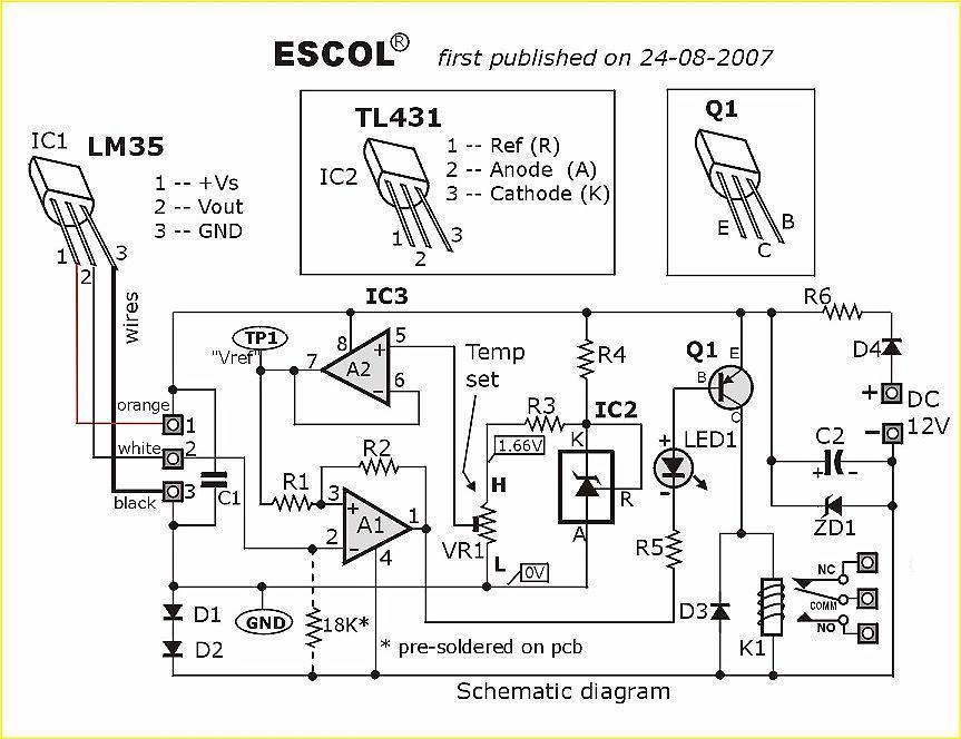
LM35 Sebagaii Sensor Suhu

Ini merupakan sebuah sirkuit elektronik yang dapat digunakan sebagai rangkaian/pengontrol
otomatis suhu. Sirkuit saklar sebuah miniatur relay HIDUP atau MATI
sesuai dengan suhu terdeteksi oleh satu keping sensor suhu LM35. Bila
LM35 mendeteksi suhu yang lebih tinggi dari tingkat preset (ditetapkan
oleh VR1), maka relay akan berkerja. Ketika suhu berada di bawah preset
suhu, relay adalah tidak akan memberikan tenaga kepada beban yang akan
kita gunakan.
Misalnya saja beban yang kita pakai adalah Lampu, atau kipas angin. Rangkaian ini dapat diaktifkan melalui tegangan AC atau tegangan DC 12V dengan pasokan (100mA min.)
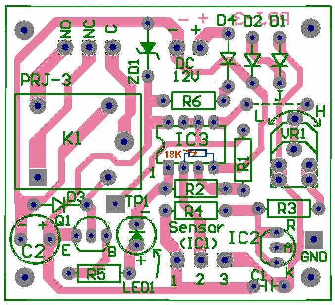
Download : schematic, layout and PCB (pdf)
Misalnya saja beban yang kita pakai adalah Lampu, atau kipas angin. Rangkaian ini dapat diaktifkan melalui tegangan AC atau tegangan DC 12V dengan pasokan (100mA min.)
Download : schematic, layout and PCB (pdf)
AT89C2051 Digital Thermometer dan jam
Thermometer adalah salah satu perangkat kesehatan yang bisa mendeteksi suhu tubuh manusia. Termometer banyak digunakan untuk memantau kesehatan salah satu pasien.
Pernahkah anda melihat termometer digital??

Silahkan lihat informasi detail dalam pembuatan AT89C2051 Digital Thermometer and Clock berikut.
Pernahkah anda melihat termometer digital??

Gambar: termometer digital dan jam
Nah, dibawah ini adalah ulasan untuk membuat termometer digital yang bisa anda buat sebagai tugas akhir (TA) maupun untuk uji coba saja. AT892051 Digital Thermometer and Clock saat ini telah banyak dikembangkan di Austria.Silahkan lihat informasi detail dalam pembuatan AT89C2051 Digital Thermometer and Clock berikut.
Circuit Description
Figure 1 depicts circuit diagram of the DigiThermo. The MCU is ATMEL 89C4051 CMOS Microcontroller having 4kB code memory, 128 bytes On-chip RAM and 8-bit Port1 and Port3. The A/D chip is HARRIS CA3162, 3-digit DVM. The A/D converter employs dual-slope integrator providing 10Hz sampling rate. Digital output sent to MCU is multiplex four bit BCD started from MSD, LSD and NSD respectively. The MSD signal was tied to P3.7 indicating first digit ready to be read. Integrating capacitor is a 330nF Polyester type. The 10k POT connected to pin13 is a gain adjustment and 50k POT to pin 8 and 9 is for zero adjustment. The input of the converter is true differential pin 11 for HI and pin 10 LO signal. Temperature was measured by a precision solid-state sensor from National Semiconductor, LM35D. The output signal is 10mV/°C. Since the A/D converter is capable of providing 0-1000mV reading with 1mV resolution, thus the converter can resolve 0.1°C (not absolute accuracy). A 100k and 0.02uF forms a first order low-pass filter used to be front-end hardware filtering. The 16x1 line LCD is connected in 4-bit interfacing to P1.4-P1.7 with control signal RS and E to P3.4 and P3.5 respectively. The +5V power supply uses a 78L05 TO92 case with external +9V adapter.
Informasi lengkap, gambar rangkaian lengkap, dan keterangan yang lebih bagus, silahkan lihat di situs ini: "http://chaokhun.kmitl.ac.th/%7Ekswichit/thermo/digithermo.htm"
Amplifer 10W Bass-boost
 Daftar Komponen :
P1 : 22K Log Potemsiometer (Dual gang for stereo)
P2 : 100K Log Potemsiometer (Dual gang for stereo)
C3, 4 : 470uF/25V
C6 : 47pF 63V ceramic ar polyester capasitor
R2, 4, 8 : 820R 1/4W
R1 : 4K7 1/4W
R3 : 500R 1/2W
R5 : 82K 1/4W
R6, 7 : 47K 1/4W
R9 : 10R 1/2W
R10 : 0,22 4W(wirewound)
C1, 8 : 470nF 63V polyester capasitor
C2, 5 : 100uF/25V
C7 : 10nF 63V polyester capasitor
C9 : 100nF 63V polyester capasitor
D1 : 1N4148 75V 150mA Diode
IC 1 : NE5532 Low noise Dual Op-amp
Q1 : BC547B 45V 100mA NPN Transitor
Q2 : BC557B 45V 100mA PNP Transitor
Q3 : TIP42A 60V 6A PNP Transistor
Q4 : TIP41A 60V 6A NPN Transistor
J1 : RCA audio input socket
Komponen Power Supply :
R1 : 1K5 1/4W
elco : 4700uF/25v
D : 100V 4A Diode bridge
Led merah
T : Centertap tranformer 2A 20V
Rangkaian download PIC
Hardware


Hardware

Skema rangkaian (klik pada gambar untuk lebih jelas)

Tidak ada komentar:
Posting Komentar