Minggu, 24 Juni 2012

JAM DIGITAL menggunakan mikrokontroler

Mungkin bagi sebagian pembaca Jam Digital merupakan hal yang sangat sederhana atau sudah terlalu umum, tapi dari Jam Digital bisa dipelajari prinsip-prinsip dasar kontrol dengan microcontroller, antara lain  sistem tampilan 7 ruas dan pemakaian ti­mer.
Klik pada gambar untuk ukuran sebenarnya


Rangkaian lengkap Jam Digital ini terlihat pada Gambar 1, dilengkapi 4 buah tampilan 7 ruas LED untuk menampilkan waktu, terdiri atas angka-angka puluhan jam, satuan jam, puluhan menit dan satuan menit. Tombol SW1 dan SW2 dipakai untuk mengatur tampilan waktu, saat SW1 ditekan angka pada tampilan jam akan bertambah setiap detik, sedangkan SW2 dipakai untuk mengatur angka tampilan menit dengan cara yang sama.
Kristal 12 MHz dan kapasitor C1 dan C2 membentuk rangkaian oscilator pembangkit frekuensi kerja AT89C2051, rangkaian ini merupakan rangkaian baku, artinya bentuk rangkaian oscilator ini selalu seperti ini untuk semua rangkaian AT89C51, kecuali untuk keperluan yang lain nilai kristalnya saja yang mungkin berbeda.
Kombinasi kapasitor C3 dan tahanan R8 juga merupakan rangkaian baku, komponen ini dipakai untukmembentuk rangkaian ‘power on reset’, artinya rangkaian yang akan otomatis me-reset AT89C2051 setiap kali AT89C2051 mulai menerima sumber daya listrik.
Melihat rangkaian pada Gambar 1, memang tidak bisa dijelaskan bagaimana Jam Digital ini bekerja, karena rangkaian itu hanyalah bagian tampilan dan tombol pengatur waktu waktu saja, ‘Jam’ yang sesungguh­nya berupa program yang disimpan di dalam ROM yang ada di dalam IC AT89C2051.

Program lengkap Jam Digital ini, berikut dengan gambar skema dan gambar PCB dalam format OrCAD 9, bisa download disini
[WaterPump.gif]

alat uji X'tal

Parts

  • R1,R7 1 M
  • R2,R3 5,6 k
  • R4 220 K
  • R5 1 k
  • R6 220
  • C1,C2 220 pF
  • C3,C4 10 F/25V RSM
  • C5 100 nF
  • C6,C7 33 pF
  • D1 LED 5 mm, yellow
  • D2 1N4148
  • T1 BC547C
  • IO1 4060
  • IO2 74HC4060
  • IO3 78L05
  • S1 push button (normally open)
  • S2 Two-positional switch 
Detail bisa Anda lihat disini...!
SELAMAT MENCOBA .... !
Artikel yang berhubungan :

Assembly Instructions: Kits #1-4

Assembly Instructions: Kits #1-4
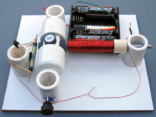
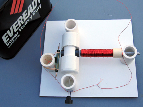
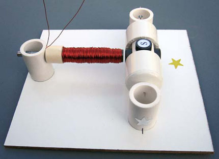
Motor, assembled from Kit #4
Motor, assembled from Kit #1 


Instructions

  1. Insert the T-pin into one of the caps.
  2. Insert T-pin into the cap
  3. Insert the rotor core into the same cap as shown below. Apply some pressure to push the rotor core approximately 1/2" (10-12mm) into the cap.
  4. Insert rotor core into the cap
  5. Put in the wooden insert.
  6. Put in round wooden insert
  7. Insert the pushpin into the other cap.
  8. Pushpin in another cap
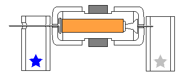
  9. Put everything together as shown below. Push the caps towards each other until they cannot move any more. The T-pin must be secured firmly. This process may require some strength. Be careful not to bend the T-pin or poke yourself.
  10. Assembled rotor
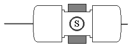
  11. Glue the magnets to the flat surfaces of the rotor core with the letter ‘S’ facing outside. If you purchased the kit with 4 magnets and want to try 2 magnets first, glue them to the opposite sides. Straighten the T-pin if necessary. You can check it by spinning the rotor between your thumb and index finger. Again, be very careful.

    All kits have magnets with the South pole marked. If you want this side to look better you may cut out the white glossy round labels that are provided and paste them to the marked sides. You may do it before attaching the magnets to the rotor. It is recommended to use regular white glue or a glue stick on the labels for better results.
  12. Rotor with magnets attached
  13. Insert the rotor into the stands marked with blue and silver stars as shown below. Hold the stands and test to see if rotor spins freely. Make final adjustments to the T-pin if necessary.
  14. Rotor on stands
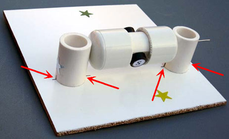
  15. Glue the stand with the silver star to the board. Try to cover the corresponding star completely. Align the marks on the stand with the line on the board as shown below. Note that the star's position and the marks are approximate, sometimes you need to move the stands slightly to achieve the lowest friction. Keep in mind that super glue bonds instantly, so try to be as accurate as possible in these procedures.
  16. Rotor on board
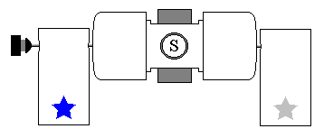
  17. Insert the rotor into the stand marked with the blue star. Glue it to the board the same way as the first stand. Leave a gap of about 1/16" (1/32", or 0.8mm on each side) between the rotor and the stands. Test again to see if the rotor spins freely. At this time, or later, you may take the rubber plug and fix it as shown below. You can glue different things to the outer flat surface of the plug. Try to be accurate, redo this step if necessary.
  18. Rotor on stands with rubber plug attached
  19. If you purchased the experimentation kit #2 or #3, instead of steps 10-12 for this kit, follow these instructions. After that, please, come back to this page and continue the assembly instructions from step 13.

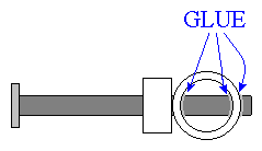
    Otherwise, insert the nail into the stand with the green star. If it is loose you may apply glue as shown below.
  20. Nail, glued to electromagnet stand
  21. Cut two pieces of wire 9" (22-23cm) long**. Leave them for now - they will be used for connecting the reed switch. All remaining wire on the spool should be used to wrap around the area between the tape and the head of the nail.
    • Tape one end of wire leaving about 6" (15cm) open*. You may use the tape that is already on the nail.
    • Wind all the wire in one rotational direction (either clockwise or counterclockwise) moving back and forth along the nail. Try to be as accurate as possible. Do not let the wire slide off the end of the electromagnet.
    • Tape the second end of the wire using the same tape. Both open ends of wire should be about 6" (15cm) long*.
    • Clean about 1" (2-3cm) of the wire tips with fine sandpaper (included) or a sharp knife to remove the insulation.
    ** 12" (30cm) if your kit does not include a battery holder.
    *   10" (25cm) if your kit does not include a battery holder.
    Electromagnet
    Test the electromagnet! Connect one wire to "+" and another wire to "-" of the battery. If electromagnet is assembled correctly the head of the nail should attract metal objects such as paper clips, small nails, knife blade, etc.
  22. Glue the electromagnet to the board as shown below. Turn the rotor slowly to see if the magnets hit the electromagnet. If one or more do, move the electromagnet back until there is a 1/16" (1.5mm) gap between the electromagnet and the closest magnet on the rotor.
  23. Rotor and electromagnet assembled on the board
  24. If you are assembling the Kit #8 please do steps 13-17 from Assembly Instructions: Reed Switch Motor With Transistor instead. After that please come back to this page and continue from step 18. For kits #1-4 follow these instructions:

    Attach the self-sticking felt pad to the reed switch stand as shown. This soft pad decreases the reed switch vibration thus decreasing the sound it generates.
  25. Felt pad on a reed switch stand
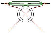
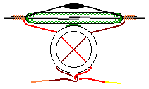
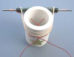
  26. Take the two pieces of wire you cut earlier in step 11 and clean the wire tips to remove the insulation. Clean about 1 1/2" (4cm) on one end and 1/2" (12mm) on the other end of each wire piece. If you want to use ZNR go to step 15, otherwise wind longer bare ends tightly around outside contacts of the reed switch as shown in the first diagram. Insert the reed switch wires into its stand as shown in a second picture. Be careful not to break the reed switch, it is very fragile. Twist the wires as shown below in diagram 3.
  27. Diagram 1: How to attach wires to a reed switch
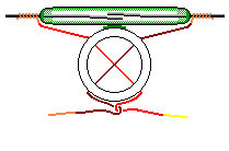
    Diagram 2: Reed switch on a reed switch stand          Diagram 3: Reed switch on a stand with twisted wires
  28. If you want to experiment with higher voltages (up to 15 Volts) or make much more reliable motor you may add a ZNR. The ZNR is a small electronic part that absorbs the spark inside the reed switch. The ZNR is not required for the motor to work. Skip this step if you are not adding ZNR at this time.

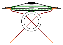
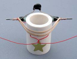
    Wind longer bare wire ends tightly around outside contacts of the reed switch and the ZNR as shown in the first diagram. Insert the reed switch wires into its stand as shown in a second picture. Be careful not to break the reed switch, it is very fragile. Twist the wires as shown below in diagram 3.
  29. Diagram 1: Connecting ZNR to the reed switch
    Diagram 2: Reed switch with ZNR on a reed switch stand            Diagram 3: Reed switch with ZNR on a stand with twisted wires
  30. Use rubber band to prevent the reed switch from moving.
  31. Fix reed switch position (shown without ZNR)    Fix reed switch position (shown with ZNR)
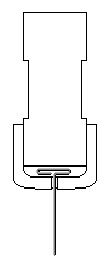
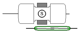
  32. Glue the reed switch holder to the base. It should be located at a distance of about 1/8" (3mm) from the closest magnet covering the gold star on the board. Check the rotation of the rotor to make sure that it does not hit the reed switch. IMPORTANT: The most sensitive part of the reed switch is not in the middle of it, but more to the side as shown below. You should hear a clicking sound when each magnet passes by the reed switch, otherwise move the reed switch a little closer to the magnets until all four can turn the reed switch on.
  33. Reed switch position
  34. If your kit does not include a battery holder, skip this step. You will need to connect your motor to any 1.5-12 Volts DC power source. 6 Volts lantern battery is a good choice as they last longer and it is easy to connect them. You may see how this battery is connected in Assembly Instructions: Simple Motor You Can Build Yourself.

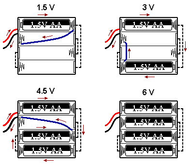
    Attach the battery holder to the board. The battery holder allows you to experiment with 4 different voltage settings (1.5, 3, 4.5, and 6V DC). You will need 4 AA size batteries.

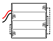
    To understand how the jumper wire works let's take a look at the connections inside the battery holder:
  35. Empty battery holder
    The following diagram shows how to get 1.5, 3, 4.5, and 6 Volts using 1, 2, 3, or 4 batteries and a jumper wire shown in blue color. Arrows show the current flow for 1.5, 3, and 4.5 Volts settings. Could you trace the current when all 4 batteries are inserted (there is no jumper wire in this case)?
    Jumper connections
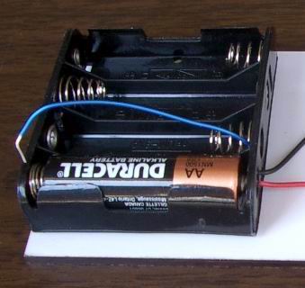
    Insert bare ends of the jumper wire between the spring and plastic case to make a good contact and hold them in place. This is how the jumper wire is actually used for 1.5 Volts experiments (one end is disconnected and may serve as on/off switch):
    1.5 Volts jumper wire connection
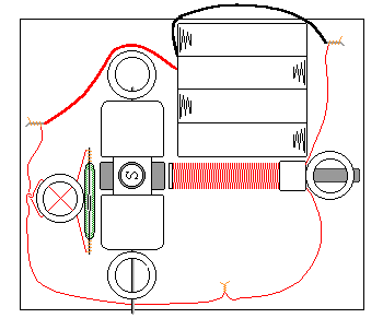
  36. Before connecting everything together connect both wires from the electromagnet to the battery. If the electromagnet doesn’t repel the permanent magnets away, switch the wires. When it repels, disconnect one wire and connect it to the reed switch. Connect the other end of the reed switch to the battery. You may tape the wires to the board using scotch tape. The wiring diagram for kits #3 and #4 is shown below:
Wiring diagram for Kits #3 and #4
Start with 1.5V. If the motor does not work, increase the voltage to 3V. If it doesn’t help, ensure that the rotor rotates freely and check all the connections – it is important to clean the insulation thoroughly. Make sure the batteries are fresh and connected properly. If the motor still does not work – click here for troubleshooting.

It is easy to change and control the speed of this motor with only a few additional parts. Experimentation kits allow you to add a speed control unit and conduct other experiments.

CONGRATULATIONS! You have finished assembling this electric motor! Click here for Experiments and Applications

Build It Yourself

Anda akan membutuhkan bahan-bahan untuk membangun motor:
Electromagnet assembly    Satu buluh saklar - saklar buluh tujuan umum dapat digunakan, namun jika Anda seorang pemula sangat dianjurkan untuk menggunakan switch buluh besar dan kuat dalam desain Anda. Lebih kecil buluh switch sangat rapuh, tidak dapat berlangsung cukup lama, dan sangat sulit untuk menghubungkan mereka tanpa lead solder mereka. Anda dapat memerintahkan sulit untuk menemukan tugas berat buluh switch yang sesuai untuk pemula di situs kami.
    
Dua magnet. Anda dapat membeli magnet keramik dari Radio Shack (diameter: 1/2 ", tinggi: 1/4"). Mereka menjual kelas 1 magnet sebesar $ 1,99. Kami menawarkan sepasang kelas 5 magnet sebesar $ 1,50. Kelas magnet yang lebih tinggi berarti lebih tinggi fluks magnetik, atau kekuatan, dan karena itu lebih dapat diandalkan operasi buluh switch.
    
Spool kawat magnet. Anda bisa mendapatkan ini di Radio Shack - mereka menjual satu set tiga gulungan yang berbeda untuk $ 6,59. Gunakan mengukur kawat menengah; anda perlu hampir semua itu. Anda juga dapat memesan gulungan kawat yang tepat pada situs ini untuk $ 3,95.
    
Anda dapat menambahkan ZNR untuk motor Anda. Ini adalah bagian kecil yang menyerap percikan di dalam saklar buluh dan memperpanjang hidup motor secara signifikan. ZNR tidak diharuskan untuk motor untuk beroperasi tetapi jika Anda ingin membuat motor jauh lebih dapat diandalkan Anda juga dapat memerintahkan ZNR di sini.
    
Sebuah gabus dari botol anggur atau sampanye. Anda tidak perlu meminumnya untuk mendapatkan gabus!
    
Jarum. Ini harus lebih dari gabus.
    
Baterai. 6 Volt baterai lentera adalah pilihan yang baik karena mereka lebih lama dan mudah untuk menghubungkan mereka, tetapi bahkan 1,5 volt baterai mungkin cukup cukup untuk menyediakan operasi yang handal.
    
Dua dorongan pin.
    
Tape. Listrik disarankan, tetapi scotch atau masking tape halus.
    
Panjang kuku (3 "- 6", 4 "direkomendasikan) untuk elektromagnet.
    
Duct tape.
    
Lem.
    
Dua kotak korek api.
    
Sepotong karton perusahaan atau bahan serupa untuk dasar.
    
Sepotong kecil amplas halus, atau pisau tajam. Digunakan untuk menghapus isolasi dari kawat.
    
Dua buku hardcover kokoh atau kotak kardus.
    
Opsional: tang, paku kecil, dan ringan.
Baca semua instruksi hati-hati dan memeriksa Aturan Keamanan sebelum Anda mulai!

  
Final assembly Ambil paku dan membungkusnya dengan pita untuk membuat lapisan sekitar 1/2 "(12mm) tebal dengan diameter pada jarak 1 - 2" (3-5cm) dari kepala kuku.

    
Kuku
    
Potong kawat 10 "(25cm) panjang Biarkan untuk saat ini -. Anda akan membutuhkannya nanti Semua kawat yang tersisa pada spool harus digunakan untuk membungkus daerah antara tape dan kepala kuku..
        
Tape salah satu ujung kawat meninggalkan sekitar 10 "(25cm) terbuka.
        
Angin semua kabel dalam satu arah putaran (baik searah jarum jam atau berlawanan) bergerak maju mundur sepanjang kuku. Cobalah untuk seakurat mungkin. Jangan biarkan slide kawat dari ujung elektromagnet.
Rotor and magnets
        Tape kedua ujung kawat dengan menggunakan pita yang sama. Kedua ujung terbuka dari kawat harus sekitar 10 "(25cm) panjang.
        
Bersihkan sekitar 1 1/2 "(4cm) satu tips kawat dengan amplas halus atau pisau tajam untuk menghapus isolasi.
Reed switch on the box
    Gulungan
    
Uji elektromagnet! Hubungkan salah satu kabel untuk "+" dan kawat lain untuk "-" baterai. Jika elektromagnet dirakit dengan benar kepala kuku harus menarik benda logam seperti klip kertas, kuku kecil, pisau, dll
    
Tape ujung terbuka dari kuku untuk kotak korek api itu.

    
Elektromagnet
    
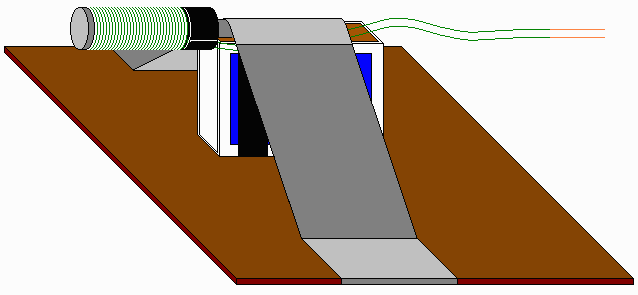
Menggunakan selotip menempel kotak korek api untuk papan seperti yang ditunjukkan di bawah ini.

    
Elektromagnet perakitan
    
Membuat penyok kecil di tengah pushpin masing-masing. Gunakan satu pushpin membuat penyok di tangan yang lain, atau memegang paku dengan tang, panas itu menggunakan lebih ringan, dan tekan ujung tajam panas kuku ke tengah pushpin tersebut.

    
Pushpin
    
Masukkan dua paku payung ke dalam dua buku hardcover atau kotak kardus seperti yang ditunjukkan di bawah ini. Pusat dari masing-masing pushpin harus pada tingkat yang sama dari permukaan dasar sebagai pusat elektromagnet.

    
Buku
    
Ambil gabus dan tongkat jarum melalui pusat di satu sisi dan memastikan bahwa itu keluar di tengah juga. Cobalah untuk menjadi akurat, mengulang langkah ini jika perlu. Neraca gabus sangat penting karena mempengaruhi kinerja motor.

    
Rotor
    
Menemukan kutub yang sama pada magnet dan menandainya. Kutub yang sama (Utara - Utara, atau Selatan - Selatan) mengusir, sedangkan kutub yang berbeda menarik. Cari memukul mundur dua sisi - mereka harus menghadap luar. Lem magnet ke sisi berlawanan dari gabus. Ini benar-benar tidak masalah jika Utara atau Selatan tiang menghadap ke atas selama mereka adalah sama.

    
Rotor dan magnet
    
Ambil 10 "(25cm) sepotong kawat (lihat langkah # 2) dan menghapus sekitar 1 1/2" (4cm) isolasi dari kedua ujungnya. Angin satu ujung telanjang erat di kontak luar dari saklar buluh. Tape saklar buluh untuk kotak korek api seperti yang ditunjukkan di bawah ini.

    
Reed switch pada kotak
    
Masukan stator (elektromagnet di dasar dan buku-buku dengan pin terpasang) dan rotor (gabus dengan jarum dan magnet terlampir) bersama-sama seperti yang ditunjukkan di bawah ini. Posisikan elektromagnet sedekat mungkin dengan magnet permanen di rotor. Sesuaikan posisi buku untuk memungkinkan rotor berputar dengan bebas tanpa memukul elektromagnet.

    
Akhir perakitan
    
Sebelum menghubungkan segala sesuatu bersama-sama menghubungkan kedua kabel dari elektromagnet ke baterai. Jika elektromagnet tidak mengusir magnet permanen pergi, beralih kabel. Ketika repels, lepaskan satu kawat dan terhubung ke saklar buluh. Hubungkan ujung lain dari saklar buluh ke baterai seperti yang ditunjukkan pada gambar di atas.
    
Jika Anda ingin bereksperimen dengan tegangan tinggi atau membuat motor jauh lebih dapat diandalkan Anda dapat menambahkan sebuah ZNR. ZNR adalah bagian elektronik kecil yang menyerap percikan di dalam saklar buluh. Hubungkan paralel ZNR ke saklar buluh seperti yang ditunjukkan pada gambar berikutnya:
Connecting ZNR to the reed switch
    Menghubungkan ZNR ke saklar buluh

    
ZNR tidak diharuskan untuk motor untuk bekerja. Tegangan lebih tinggi membuat motor berjalan lebih cepat tapi bahkan dengan ZNR itu tidak dianjurkan melebihi 15 Volt.
Jika Anda membawa dekat buluh beralih ke magnet motor harus mulai bekerja segera. Jika tidak bekerja memeriksa semua koneksi - sangat penting untuk membersihkan isolasi secara menyeluruh, pastikan baterai baru dan terhubung dengan benar; memindahkan buku untuk memungkinkan rotasi bebas. Jika masih tetap tidak bekerja - memeriksa bagian Pemecahan Masalah.
SELAMAT! Anda telah selesai perakitan ini motor listrik! Klik di sini untuk Eksperimen dan Aplikasi.

Mini Transmitter TV

Nama Alat : Mini Transmitter TV
Deskripsi Fungsi : Pemancar TV mini ini menggunakan band VHF sesuai untuk pemancar lokal dalam suatu acara/kegiatan yang membutuhkan tampilan visual.

Cara kerja : 
Audio input gunakan modulasi umpan negatif dan tempatkan modulasi video pada posisi PAL . TV penerima menggunakan sistem BG. Frekuensi kerja rangkaian ini diantara LHF dan VHF (antara 54-216MHz). Modulasi sinyal suara diantara 5.5 -6MHz melalui tuning C5. dengan kualitas modulation is FM. Part list : 
Source : 
SELAMAT MENCOBA... 
Kategori lain yang berhubungan : 
Alat Uji Alat Ukur Audio Inverter Oscilator Power Supply Radio Transcevier Sensor Timer Hobi HOT News Household Project Quick Repair
Read more >>